555 🔬
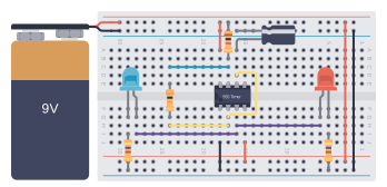
The LM555 operates in both astable (oscillator) and monostable (one-shot) modes. In monostable mode, it generates a single output pulse of controlled duration when triggered. In astable mode, it produces continuous square wave oscillations with adjustable frequency and duty cycle. The timing is precisely controlled by external resistors and capacitors.


Key Features
- Direct replacement for SE555/NE555
- Timing from microseconds through hours
- Operates in both astable and monostable modes
- Adjustable duty cycle
- Output can source or sink 200 mA
- Output and supply TTL compatible
- Temperature stability better than 0.005% per °C
- Normally on and normally off output
- Available in multiple package types
- Wide supply voltage range (4.5V to 18V)
- High current output capability
Applications
- Precision timing circuits
- Pulse generation
- Sequential timing
- Time delay generation
- Pulse width modulation (PWM)
- Pulse position modulation
- Linear ramp generator
- Astable and monostable multivibrators
- Voltage-controlled oscillators
- Missing pulse detectors
- Frequency dividers
- LED flashers and blinkers
Notes
When operating in astable mode, the frequency and duty cycle are controlled by two external resistors and one capacitor. In monostable mode, the output pulse width is determined by one resistor and one capacitor. The Reset pin should always be connected to VCC unless reset functionality is needed. The Control Voltage pin can be left floating or connected to a bypass capacitor for noise immunity.